



Details
Strawberry-Pi: Building my own handheld gaming device
This project started while I was working on a mod for a game. I was playing it on my old Nintendo 3DS XL, and I noticed that the display resolution didn’t scale particularly well with the original game’s resolution. The emulator’s scaling and filtering options made some of the custom sprites I’d created look washed out, which was frustrating when I’d put effort into getting them to look right.
That got me thinking about building my own handheld emulation device. I’ve always loved handheld consoles, and I’ve owned quite a few over the years, from my purple Game Boy Color to the Game Boy Advance SP, the original Nintendo DS, the DS XL, and eventually the 3DS XL. I’ve also been interested in hardware development and low-level programming for a while, so building a handheld seemed like a good opportunity to combine those interests.
Choosing the platform
I initially looked at existing handheld emulation devices, particularly the many Android-based handhelds coming out of China. There are some interesting devices on the market, but I had a couple of reservations.
One concern was the way some devices are sold with large collections of preloaded games, without much clarity about whether the original creators are being compensated. As a game developer myself, I believe people should buy the games they want to play and support the people who make them. If you want to emulate games you already own, making your own backups is a much better approach than relying on questionable preloaded collections. Since I do believe that once you paid for something its yours to do with as you please.
I was also hesitant about trusting custom Android builds on devices where I had little visibility into how the software was maintained. I wanted more control over the software running on my device, as well as the freedom to experiment with it.
So, rather than buying a ready-made handheld, I decided to build one myself.
The project is called Strawberry-Pi, and at its heart is the Raspberry Pi Compute Module 5 (CM5).
I considered several other platforms, including the Raspberry Pi Zero 2 W and modules from Radxa. The Zero 2 W would make it possible to build a smaller and potentially more power-efficient device, but I wanted some extra performance and flexibility for things beyond emulation. I didn’t have a completely defined end goal at that point, so having some headroom seemed worthwhile. Radxa’s modules were also worth considering, but the Raspberry Pi ecosystem and its larger community made the CM5 a more comfortable choice.
The Compute Module form factor is particularly appealing for a project like this. Compared with using a complete Raspberry Pi 5, it gives me more freedom to design a compact custom motherboard around the components I actually need.
Power consumption is one of the main challenges with using the CM5 in a battery-powered device. However, with some tuning, such as reducing clock speeds and disabling features that aren’t needed, I hope to keep consumption at a reasonable level without sacrificing too much performance.
Designing the electronics
I’ve split the electronics into several subsystems. This makes it easier to develop and test each part independently before bringing everything together on a single motherboard.
Audio
The audio system takes digital audio from the CM5 over its I²S interface and sends it to a DAC, which converts it into an analogue signal.
From there, the signal is split between two amplifier paths: one for the built-in speakers and another for the headphone output. The speaker amplifier is designed to deliver around 1 W, while the headphone amplifier handles the headphone output.
The headphone jack also has switching functionality, so connecting headphones disables the speakers and routes audio to the headphone output instead. This keeps the behaviour simple and familiar.
I/O and controls
The controls are designed to be straightforward and responsive. The face buttons and bumpers work by pulling a voltage line low when pressed, allowing the system to detect button inputs.
The CM5 doesn’t expose enough GPIO pins for everything I want to connect, so I’ve added an I/O expander over I²C to provide more inputs without using up all the available pins.
The analogue controls need a different approach. The joysticks use potentiometers to report their positions, while the triggers use Hall-effect sensors. These analogue signals are read through analogue-to-digital converters (ADCs), with the resulting measurements communicated to the CM5 over I²C.
Using Hall-effect sensors for the triggers should provide smooth analogue input without relying on the mechanical contact used in a conventional potentiometer. It also gives me flexibility in how the triggers are calibrated and interpreted in software.
Power management and battery life
Power management is particularly important in a handheld device, both for safety and for getting a useful amount of play time out of the battery.
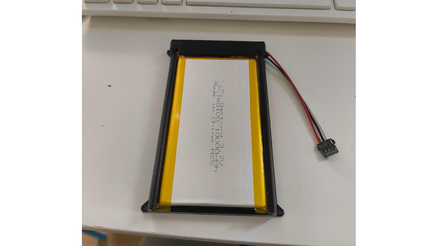
The handheld uses a 10,000 mAh LiPo battery with a nominal voltage of 3.7 V, giving it around 37 Wh of stored energy. My target is 5–6 hours of battery life during normal use, roughly comparable to a Nintendo DS.
The USB-C input is designed for 5 V, without USB Power Delivery negotiation. I’ve used two eFuses to protect the battery and USB-C power paths, allowing the higher of the two input voltages to supply the system. When USB-C power is connected, the battery is disconnected from the main VSYS power path.
VSYS then feeds a regulator that provides a stable 5 V supply for the system. Additional regulators generate the 3.3 V and 1.8 V rails required by the other components, with smaller local power domains where needed.
Charging is enabled only when USB-C power is present, using the power-good (PG) signal from an eFuse. I’ve also included current sensing after the 5 V regulator, allowing the system to monitor its power consumption and reduce the charging current when the handheld itself is drawing more power. The goal is to keep the total draw within the default USB-C power budget of 5 V at 3 A.
For context, the CM5’s idle power consumption is around 2.3 W in Jeff Geerling’s testing, while its peak consumption can be considerably higher. I’m budgeting for a 5 V, 3 A supply, giving a maximum power budget of 15 W. If the system were drawing that much continuously, the battery would last roughly two hours after allowing for conversion losses.
At idle, the CM5 itself draws around 400–500 mA at 5 V, or 2–2.5 W. Based on the battery’s 37 Wh capacity, that suggests roughly 14.5 hours at the higher end of that idle draw, before accounting for conversion losses and the additional power consumed by the display, audio, and other components.
Normal gameplay should fall somewhere between those extremes, making 5–6 hours a reasonable initial target. These are estimates rather than measured results, though; I’ll need to test the complete device to see how close I get.
Display and backlight
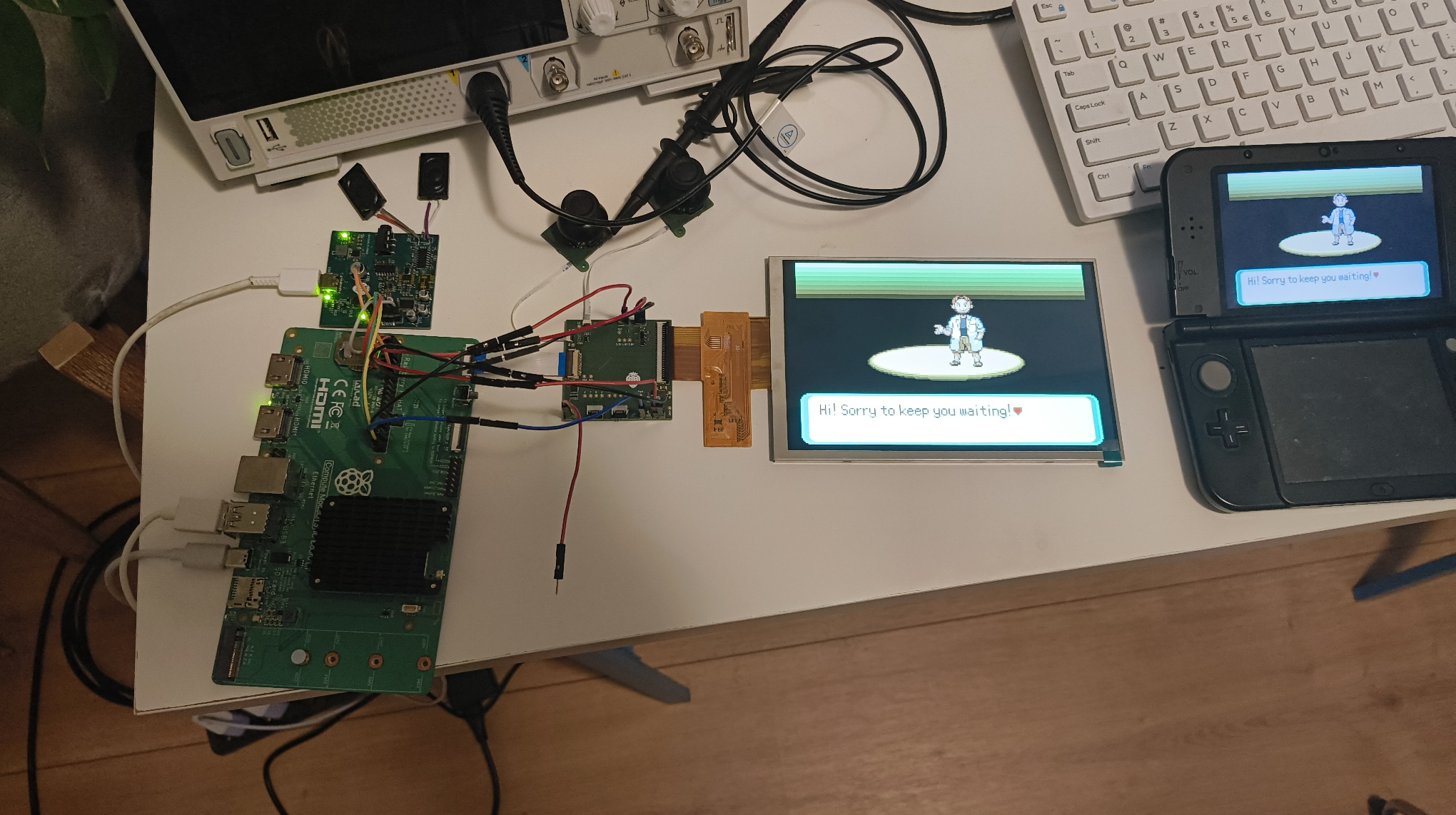
For the display, I was able to obtain samples of a 800 × 1280 display module from a supplier. The resolution was one of the main reasons I chose it.
When rotated into landscape orientation, the display becomes 1280 × 800. That works particularly well for Game Boy Advance games, which run at 240 × 160 pixels: scaling them by exactly 5× produces an image of 1200 × 800 pixels. That leaves 80 horizontal pixels for borders or other interface elements without needing to stretch the game image.
The display needs to be rotated 90 degrees in software to use it in landscape orientation, but that’s a manageable trade-off for the resolution and scaling options it provides.
The panel is rated at 1000 cd/m², which should make it bright enough to use outdoors in many conditions, although direct sunlight and reflections will still affect visibility.
I’ve also designed a separate LED driver for the backlight. Its PWM input allows brightness control while maintaining a stable output voltage. The intention is to provide smooth brightness adjustment without visible flicker, though I’ll need to verify the behaviour on the finished hardware.
Designing the enclosure
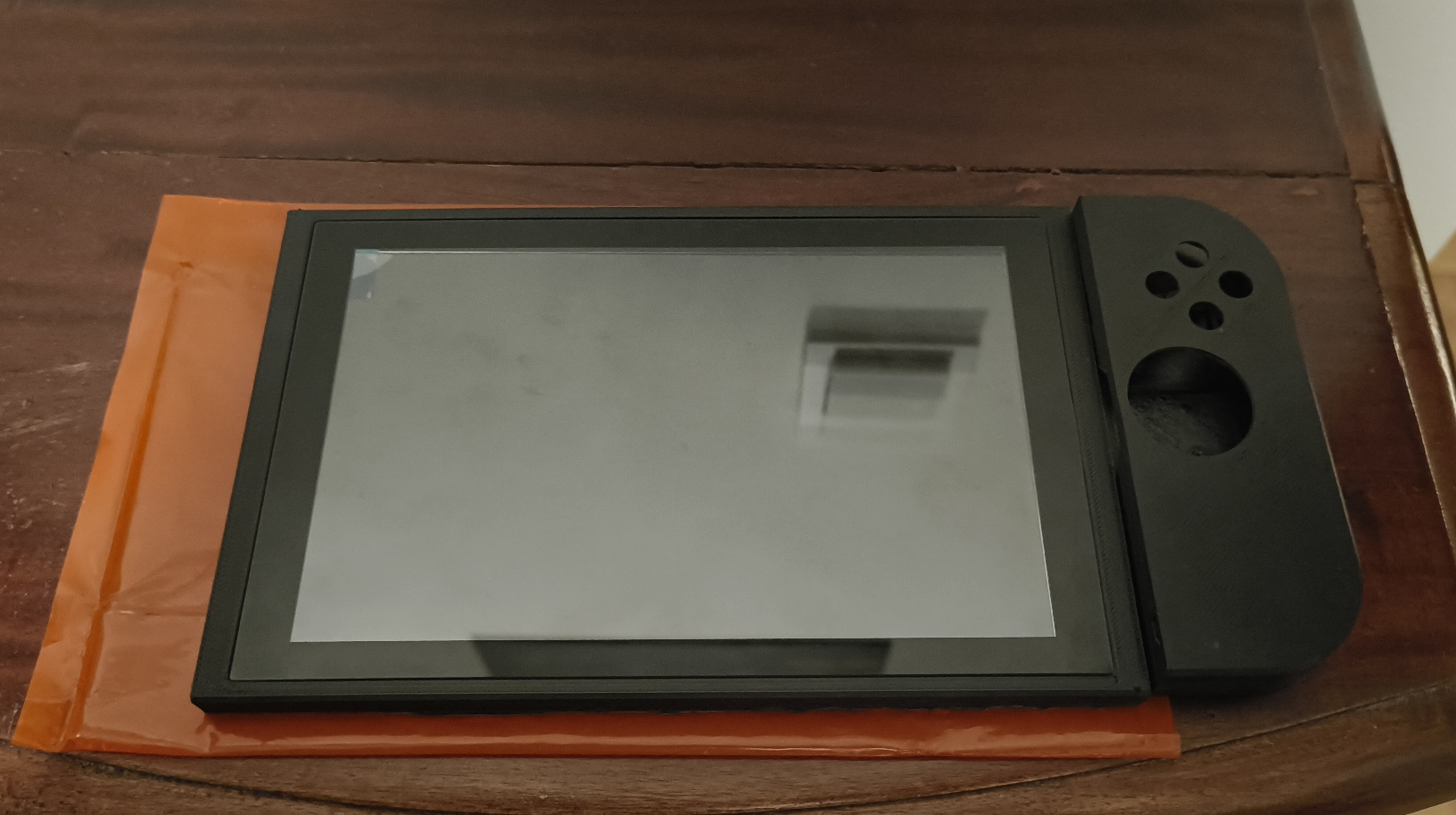
The enclosure is being designed from scratch in FreeCAD. I wanted the device to feel like a purpose-built handheld rather than a development board squeezed into a generic case.
For the overall size, I looked at devices such as the Steam Deck and Nintendo Switch. My target is somewhere between the two, but much closer to the Switch Lite in size.
I also disassembled a PS5 controller and a Meta Quest controller to get a better understanding of how their internal layouts and controls are arranged. Looking at existing hardware is useful for understanding how much space the buttons, joysticks, and supporting components actually need.
One thing I noticed when using the Switch was that its controls felt a little cramped for my hands. For Strawberry-Pi, I’ve made the face buttons slightly larger and spaced them further apart. I’ve also moved the joysticks a little closer to the display, with the aim of creating a more natural resting position for my thumbs.
Ergonomics are still something I’ll need to evaluate properly once I have a complete working prototype. At this stage, my priority is to get everything to fit and function correctly. If the device needs more substantial grips or other changes to improve comfort, I can incorporate those into a later revision.
The enclosure is designed for FDM 3D printing, so people can make their own case without needing specialised manufacturing equipment. I’m planning to use ASA rather than PLA because it is generally less brittle and offers better heat and UV resistance, which should make it more suitable for a portable device that may get warm during use.
There is one practical consideration: ASA can be more demanding to print than PLA, so anyone wanting to build the device will need a 3D printer capable of printing it, with enough build volume for the enclosure parts.
Current progress
Most of the electrical subsystems have been prototyped, and I’ve got proof of concept for each of them. The controller layout is also coming together, and I’m currently working on the enclosure around the display.
The next major step is to bring everything together onto a single motherboard. That should reduce the amount of space taken up by separate prototype boards and wiring, making it possible to work towards a slimmer and more integrated design.
I also need to design a slimmer heatsink for the CM5 so that the cooling solution fits within the enclosure while still keeping temperatures under control.
There’s still plenty to do, but getting each subsystem working independently has been an important milestone. It means I can focus on integration and refinement rather than trying to debug every part of the system at once.
The end goal: an open DIY handheld
My intention is to make Strawberry-Pi an open project. I’d like to publish the electrical schematics, PCB design files, mechanical CAD files, and assembly instructions so that anyone interested can build their own device or adapt the design for their own needs.
I’d also like to maintain a custom Linux distribution tailored to the hardware, rather than relying on an off-the-shelf operating system that may not be optimised for the device.
I’m still considering exactly how to distribute the project. One possibility is to offer a kit containing the PCBs and fasteners, leaving builders to print their own enclosure and source the remaining components. Another option would be to provide pre-printed enclosure parts to make assembly easier.
This is primarily a hobby project and a way for me to explore hardware design, embedded systems, and Linux while building something I’d genuinely enjoy using. Making the design open source means other people can learn from it, build their own, or adapt it for their own projects.
I’m also still deciding on the licensing. GPL-3.0 is one possibility for the software, while the hardware design files may be better suited to a dedicated open-hardware licence.
If you want to build your own version, experiment with the design, or use parts of it in another project, that’s exactly the kind of thing I’d like to enable. I want the work to be useful to other makers, not just something that lives on my desk.
Acknowledgements
I’d like to thank the suppliers who provided samples that helped me get the project moving:
- Midas Displays for providing display module samples.
- Konshen Glass for providing cover glass samples.
- LiPol Battery for providing LiPo cell samples.
Their support has been very helpful during the prototyping stage, and I’m grateful that they were willing to provide samples for the project.